PFXSTW6400WAD Proface HMI

Jual HMI Proface PFXSTW6400WAD | STW-6400WA

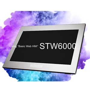
HMI Proface PFXSTW6400WAD STW-6500WA


HMI Proface PFXSTW6400WAD | STW-6400WA

HMI Proface PFXSTW6400WAD Standard product information :

Standard product information
Family
Web HMI
Series
STW6000 Series
Size
7″ Wide
Model
PFXSTW6400WAD
Global Code
PFXSTW6400WAD
Sales Status
Sale
Repair Status
✔ (Maintenance service is available, able to be maintained.)

HMI Proface PFXSTW6400WAD Display specifications

PFXSTW6400WAD Display type
TFT Color LCD
PFXSTW6400WAD Display size
7″ Wide
PFXSTW6400WAD Resolution
800 x 480 pixels (WVGA)
Effective display area
W154.08 x H85.92 mm [W6.066 x H3.382 in.]
Display colors
16 million colors*1
Backlight
White LED (Not user replaceable. When replacement is required, contact your local distributor.)
Backlight service life
50,000 hrs. or more (each in continuous operation at 25 °C [77 °F] before backlight brightness decreases to 25%)
Brightness control
16 Levels (Adjusted with touch panel)
PFXSTW6400WAD Touch panel type
Resistive Film (analog, single-touch)
Touch panel resolution
1,024 x 1,024
Touch panel lifetime
1,000,000 times or more

1*) For details about Display colors, refer to the manual for your screen editing software.

HMI Proface PFXSTW6400WAD Electrical specifications

PFXSTW6400WAD Rated input voltage
24 Vdc
Input voltage limits
19.2 to 28.8 Vdc
Allowable voltage drop
5 ms or less
PFXSTW6400WAD Power consumption
Max. 9 W
When power is not supplied to external devices: 5.5 W or less
When screen turns off the backlight (standby mode): 3.6 W or less
In-rush current
30 A or less
Voltage endurance
1,000 Vac, 20 mA for 1 minute (between power terminal and FG terminals)
Insulation resistance
500 Vdc, 10 MΩ or more (between power terminal and FG terminals)

HMI Proface PFXSTW6400WAD Environmental specifications

International safety standards
Surrounding air temperature
0 to 50 °C [32 to 122 °F]
Storage temperature
-20 to +60 °C [-4 to 140 °F]
Dust
0.1 mg/m3 (10-7 oz/ft3) or less (non-conductive levels)
Pollution degree
For use in Pollution Degree 2 environment
Corrosive gases
Free of corrosive gases
Air pressure (altitude range)
800 to 1,114 hPa (2,000 m [6,561 ft.] above sea level or less)
Vibration resistance
IEC/EN 61131-2 compliant
5 to 9 Hz single amplitude 3.5 mm [0.14 in.]
9 to 150 Hz fixed acceleration: 9.8 m/s2
X, Y, Z directions for 10 cycles (approx. 100 min.)
Concussion resistance
IEC/EN 61131-2 compliant 147 m/s2, X, Y, Z directions for 3 times
Electrical fast transient/burst
IEC 61000-4-4
2 kV: Power port (display unit)
1 kV: Signal ports
Electrostatic discharge immunity
Contact Discharge Method: 6 kV
Air Discharge Method: 8 kV
(IEC/EN61000-4-2 Level 3)

HMI Proface PFXSTW6400WAD Interface specifications

USB (Type A)
Conforms to USB 2.0 (Type A) x 1
Power supply voltage: 5 Vdc ±5 %
Output Current: 500 mA or less
Communication distance: 5 m [16.4 ft.] or less
USB (micro-B)
–The USB (micro-B) interface is disabled.
Ethernet
IEEE802.3i / IEEE802.3u, 10BASE-T / 100BASE-TX, Connector: Modular jack (RJ-45) x 2*2

2ETH1 and ETH2 have the same IP address and MAC address.

HMI Proface PFXSTW6400WAD Structural specifications

PFXSTW6400WAD Grounding
Functional grounding: Grounding resistance of 100 Ω, 2mm2 (AWG 14) or thicker wire, or your country’s applicable standard. (Same for FG and SG terminals)
Cooling method
Natural air circulation
Structure
IP65F, Type 1, Type 4X (indoor use only), Type 13 (on the front panel when properly installed in an enclosure)*3
PFXSTW6400WAD External dimensions
Rear Module: W145.6 x H108.23 xD 41.4 mm [W5.73 x H4.26 x D1.63 in] (excluding protrusions)
Display Module: W140.4 x H101.1 x D13.9 mm [W5.53 x H3.98 x D0.55 in] (excluding protrusions)
Panel cut-out dimensions
W190 x H135 mm [W7.48 x H5.31 in.]
Panel thickness area: 1.6 to 5 mm [0.06 to 0.2 in.]*4
Weight
0.8 kg [1.76 lb] or less

Note :

3*) For dimensional tolerance, everything +1/-0 mm (+0.04/-0 in) and R in angle are below R3 (R0.12 in)

4*) For dimensional tolerance, everything +1/-0 mm [+0.04/-0 in.] and R in angle are below R3 [R0.12 in.]. Even if the installation wall thickness is within the recommended range for the “Panel Cut Dimensions”, depending on wall’s material, size, and installation location of GP unit and other devices, the installation wall could warp. To prevent warping, the installation surface may need to be strengthened.

HMI Proface Lainnya